
Ferrite Beads vs 0Ω Resistors and Inductors — Which to Use for Single-Point Grounding?
Many engineers and hobbyists often confuse the applications of ferrite beads, 0Ω resistors, and inductors.
In our previous discussion, we compared these three basic components from four perspectives—appearance, schematic symbols, internal structure, and practical applications (Ferrite Beads vs 0Ω Resistors: Principles, Characteristics, and EMC Application Guide).
However, one question remained unanswered: When implementing single-point grounding, should you use a 0Ω resistor or a ferrite bead?
What is Single-Point Grounding?
Before deciding between a 0Ω resistor and a ferrite bead, we first need to clarify the concept of single-point grounding.
In a circuit, ground serves as the voltage reference point—the 0V baseline.
If there are multiple separate grounding points within a system, potential differences can arise between them.
In other words, some “grounds” may no longer be exactly 0V.
This can create ground loop currents, which in turn introduce noise into the system.
To eliminate this, all grounds must be brought together at a single common connection point.
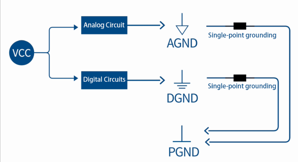
For example, in mixed-signal systems, analog and digital circuits each have their own grounds—AGND and DGND.
These two grounds can be linked at a single point.
If there is also a power ground in the system, both the analog and digital grounds can be connected to it through single-point grounding.
This approach prevents noise from digital circuits or power circuits from coupling through the ground plane into sensitive analog circuitry.
Single-point grounding works well for low-frequency circuits; for high-frequency circuits, other grounding methods may be more effective, which we won’t go into here.
The Question: Which to Use for Grounding?
Now comes the question—what component should be used for the grounding connection?
Do ferrite beads and 0Ω resistors achieve the same effect?
From our earlier discussion of component characteristics:
- Ferrite beads behave like band-stop filters.
They present very high impedance at a specific high-frequency range, converting unwanted signal energy in that band into heat, thereby providing EMI suppression and filtering.
If you can estimate the dominant interference frequency range in your circuit, you can select a ferrite bead with high impedance in that range for effective filtering. - 0Ω resistors behave more like broadband attenuators.
Since they have a small resistive property across the entire frequency spectrum, they can provide uniform attenuation without targeting a specific frequency band.
When to Use Each
If you cannot determine the interference frequency—for example:
- Your DC power input comes from a DC-DC converter or an LDO, both of which may introduce ripple.
- Your ground connection carries various mixed signals, including high-speed digital switching noise.
- Multiple noise sources with unknown frequency content are present.

In such cases, it’s safer to use a 0Ω resistor for single-point grounding.
The Core Principle
Regardless of whether you choose a ferrite bead or a 0Ω resistor, the fundamental grounding strategy is the same:
- Bring all grounds to a single reference point to minimize ground potential differences.
- Restrict ground loop currents to a localized area so they do not interfere with other parts of the circuit.
This approach is especially suitable for low-frequency and mixed-signal systems.
It’s worth checking your own PCB—what component is your single-point grounding implemented with?
IT Resource Hub » Ferrite Beads vs 0Ω Resistors and Inductors — Which to Use for Single-Point Grounding?
