
Ferrite Beads vs 0Ω Resistors: Principles, Characteristics, and EMC Application Guide
There’s a small component that can be used just like a 0Ω resistor, but it can also function like an inductor.
Can you guess what it is?
Yes—it’s the ferrite bead. Today, we’ll explore ferrite beads in detail.
To make things easier to understand, we’ll compare ferrite beads directly with 0Ω resistors.
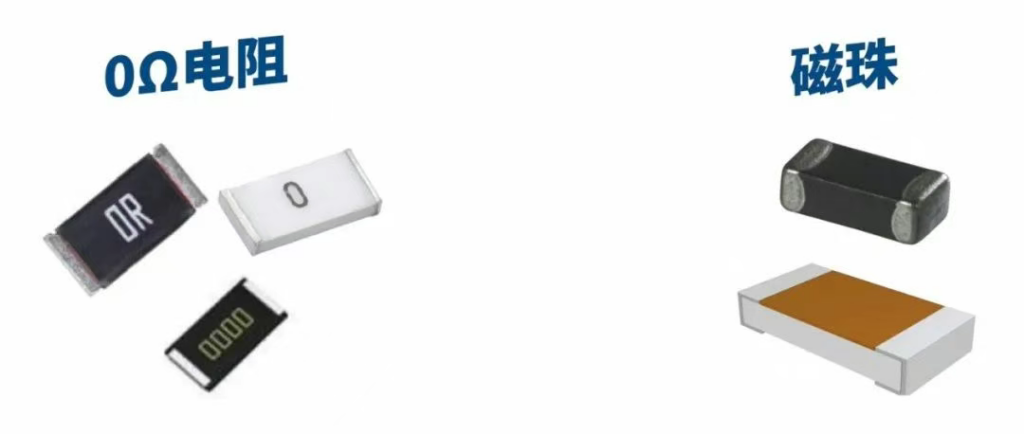
1. Appearance
Let’s first take a look at what ferrite beads and 0Ω resistors look like.
From the image above, it’s clear that although both are surface-mount components, the 0Ω resistor has a clear printed marking, just like any standard SMD resistor. Ferrite beads, on the other hand, usually have no visible markings at all.
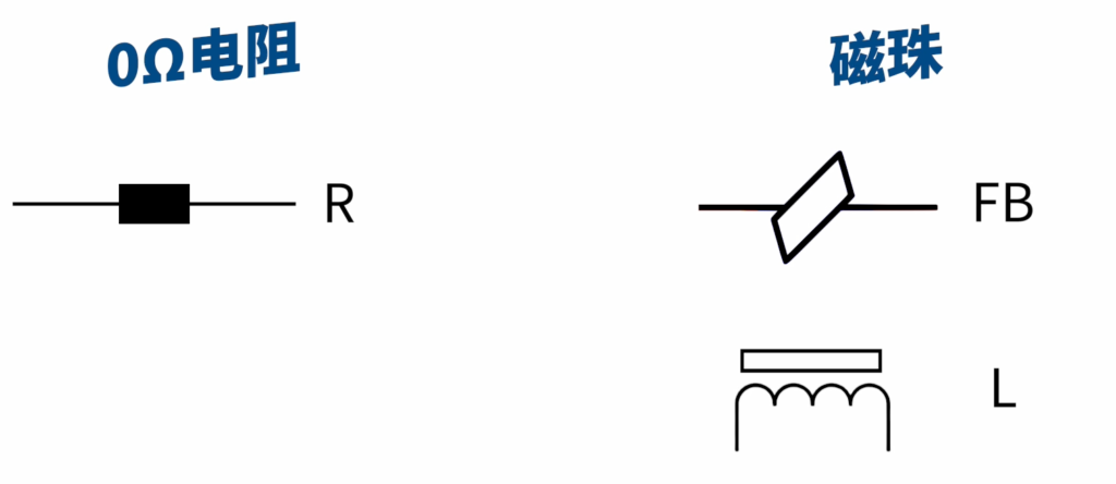
2. Schematic Symbol
On circuit diagrams, the 0Ω resistor is represented by the letter R without question.
Ferrite beads, however, have no unified symbol—some designers use FB, while others use L. Using “L” may imply it’s being treated as an inductor. The key differences between a ferrite bead and an inductor will be discussed shortly.
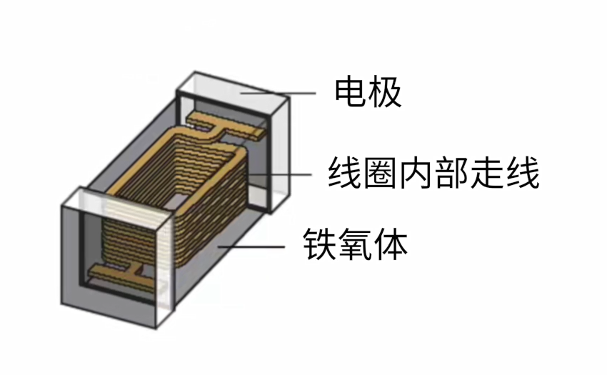
3. Internal Structure
After examining their physical appearance and schematic symbols, let’s see what they really are inside—this is their third major difference.
A 0Ω resistor, as the name suggests, is simply a resistive component. In reality, due to manufacturing tolerances and material properties, its resistance isn’t exactly zero but is extremely small.
Ferrite beads are more complex. In simple terms, you can think of a ferrite bead as an inductor, which explains why “L” is sometimes used in schematics. However, the characteristics and parameters of ferrite beads are very different from a conventional inductor.
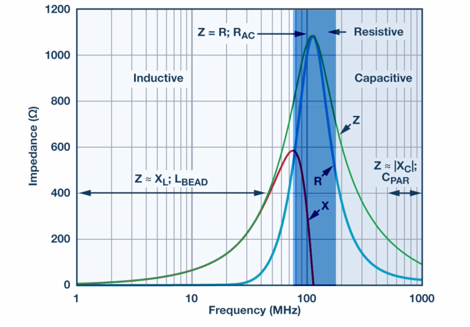
Below is a ferrite bead’s parameter chart. Two parameters are particularly important: frequency and impedance. These values represent the impedance of the ferrite bead at a given frequency. Typically, this impedance is quite high—hundreds or even thousands of ohms—yet its DC resistance is very low, often only a few milliohms.
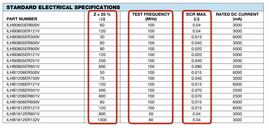
These characteristics are determined by the ferrite material itself, which is usually made from ferrite (iron oxide). Ferrite materials have high magnetic permeability, allowing the coil winding to maintain very low capacitance at high frequencies. Ferrite beads are usually used at frequencies below a certain range, as their impedance rises significantly with frequency.
The equivalent circuit model of a ferrite bead can be seen as an inductor in parallel with a resistor.
- At low frequencies, the inductor shorts out the resistor, resulting in minimal power loss.
- At high frequencies, the impedance of the inductor rises sharply, forcing current through the resistor. This causes power loss in the resistor, which is dissipated as heat—effectively converting electrical energy into thermal energy.
From this, we can see the fundamental difference:
- Ferrite bead → energy dissipation device (converts electrical energy to heat).
- Inductor → energy storage device (stores energy in a magnetic field and releases it back into the circuit).
4. Usage
Now that we understand their structural differences, let’s see how they’re used in practice.
0Ω resistor applications are numerous and varied.
Applications of 0Ω Resistors
- Convenient for debugging or tolerance design
- Used as a jumper wire
- Circuit bridging
- When circuit parameters are uncertain, replace with a 0-ohm resistor
- Measuring circuit power consumption
- Acting as a capacitor or inductor during charging
- Used as a fuse to protect against overcurrent
- Single-point grounding between analog and digital grounds
- Bridging for current return paths
- Circuit configuration
- Noise suppression
Ferrite bead applications are mainly for EMI/EMC purposes—suppressing interference and high-frequency noise. A ferrite bead can absorb high-frequency spikes and noise.
From the impedance curve, you’ll notice that at around 100 MHz, the ferrite bead’s impedance is at its maximum. This means it is most effective at absorbing signals in this frequency range, converting their energy into heat and reducing interference.
According to the formula P = I²R, the signal energy in that frequency range will drop significantly after passing through the bead, effectively filtering out the unwanted interference. If the bead’s peak impedance range matches the interference frequency, it can greatly improve EMI performance.
At DC, the resistance of a ferrite bead is extremely small—just a few milliohms. This means ferrite beads can also be used for single-point grounding. In such cases, either a 0Ω resistor or a ferrite bead could be used, but the choice depends on whether you want purely conductive connection (0Ω) or high-frequency noise suppression (ferrite bead).
IT Resource Hub » Ferrite Beads vs 0Ω Resistors: Principles, Characteristics, and EMC Application Guide
